The tall Z gantry on the Ender 3 V3 SE sways like a mast at high speed and leaves wavy layers at the top of a print. Here is how a rear support-rod kit, plus a redesigned side-mount spool holder, made the frame rock solid.
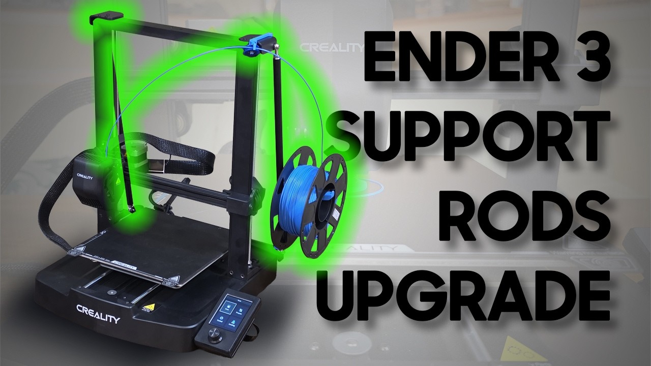
The Ender 3 V3 SE gantry sways like a mast at high speed, and side-mounting the spool alone does not fix it. Bracing the frame from the back with a triangulated support-rod kit, then re-engineering the side-mount spool holder to anchor onto that rod, killed the wobble. The high-speed stress test that used to print wavy layers came out clean.
Verdict: a rigid frame at high speedUpdate: YOOPAI has confirmed to me that they no longer stock the Support Rod Kit featured in this guide. The custom side-mount spool holder files still work for anyone who already owns the kit, and a fully 3D-printed DIY alternative may be next. See the end of this post to weigh in.
The Creality Ender 3 V3 SE and KE are incredibly fast machines for their price point, but as you push the speed settings higher a physical limitation quickly becomes obvious. That tall, unsupported Z-axis gantry starts to act like a swaying mast. Even after moving the filament spool from the top to a side-mount to lower the center of gravity, the frame is still prone to flexing.
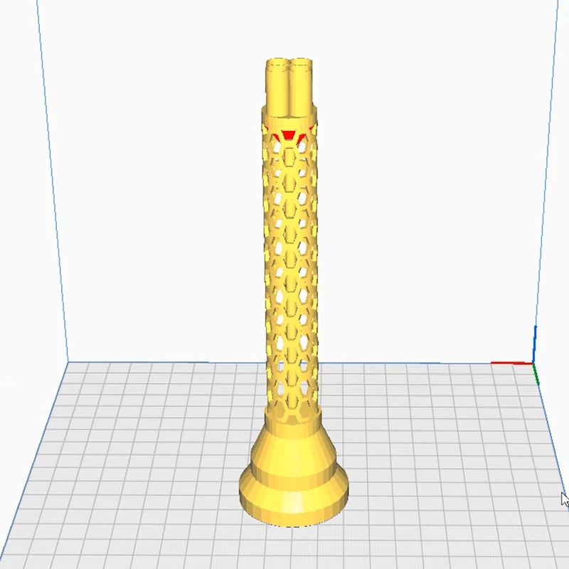
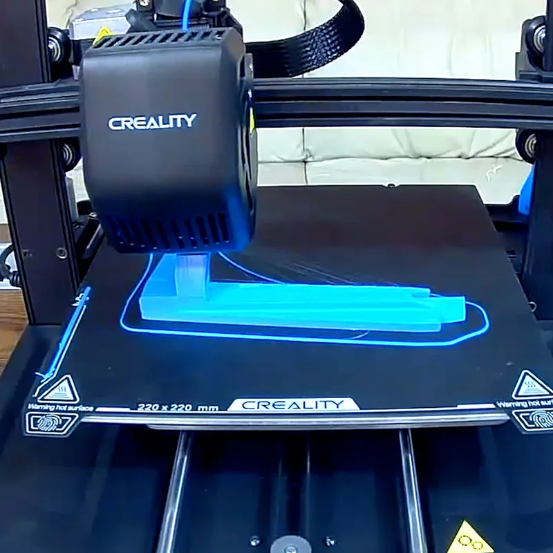
To find the breaking point, I designed a custom Z-axis stress test built around an intricate honeycomb tube. By forcing rapid direction changes and sharp corners at 220mm/s, the frame's tendency to vibrate became extremely visible, leaving wavy, out-of-place layers at the top of the print.

The fix is to build a rigid support structure using a triangulation kit. Here is how I installed the YOOPAI Support Rod Kit and re-engineered my custom side-mount spool holder to fit the new hardware.
Disclosure: This post contains affiliate links. As an Amazon Associate I earn from qualifying purchases, at no extra cost to you.
Here is everything used in this build. The support rod kit is the only paid piece that is no longer available, so the parts list below points to the free STL files and the small hardware you can still source.
The YOOPAI kit is designed specifically for the Ender 3 V3 SE and KE to brace the gantry from the back. It includes a heavy-duty steel bottom brace with zero flex, two thick steel plates for the top, frosted aluminum rods, and all the necessary hardware and tools.
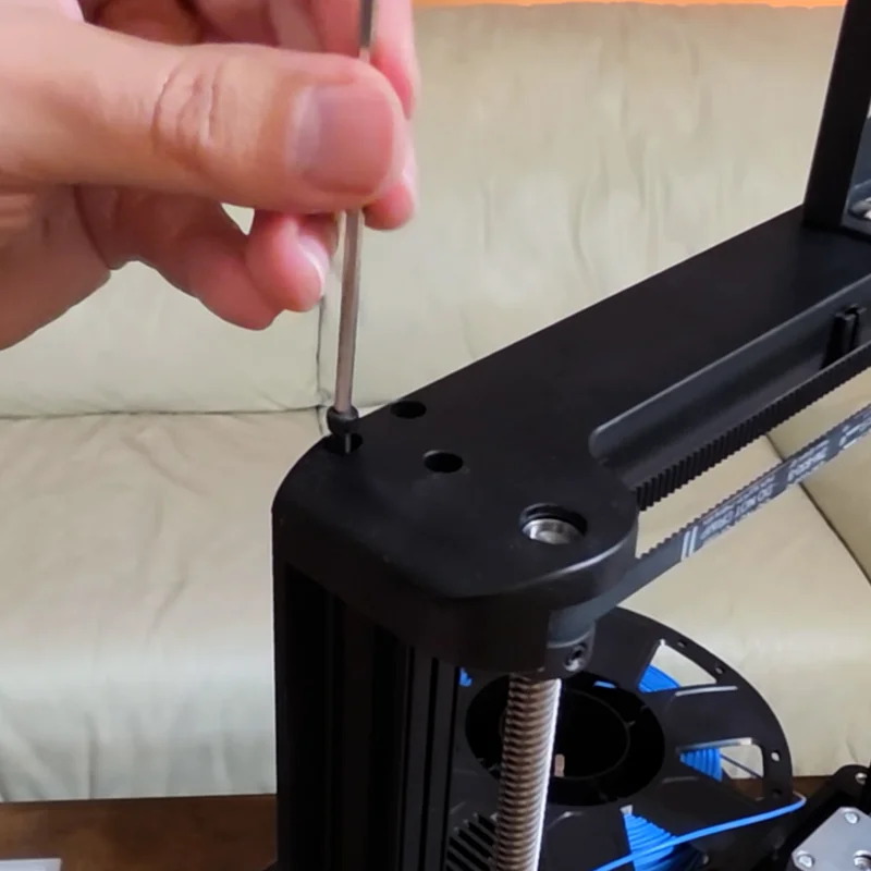
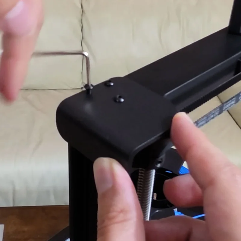
Remove the six original screws holding the top of the gantry down using a 2.5mm Allen key, then replace them with the provided longer M3x25mm screws and the new top steel plates. Work one side at a time, and note that the new screws take the 2mm Allen key instead of the 2.5mm.
Move to the back base of the printer and remove the silver drive-rod screws. Install the new bottom steel bracket using the provided M3x16mm screws. Make sure it is oriented correctly: the hump should be on top, and the wings should point forward.
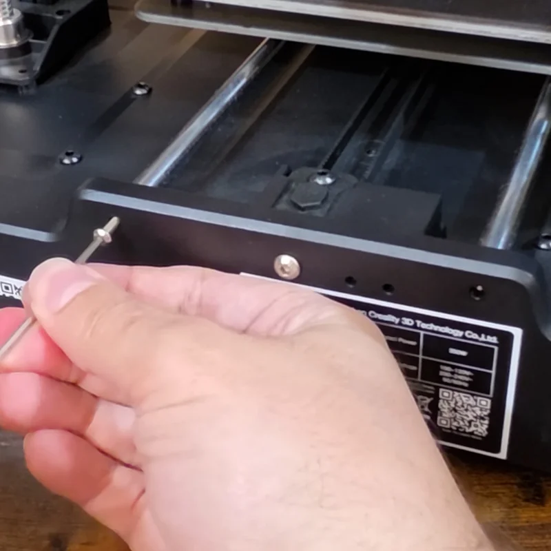
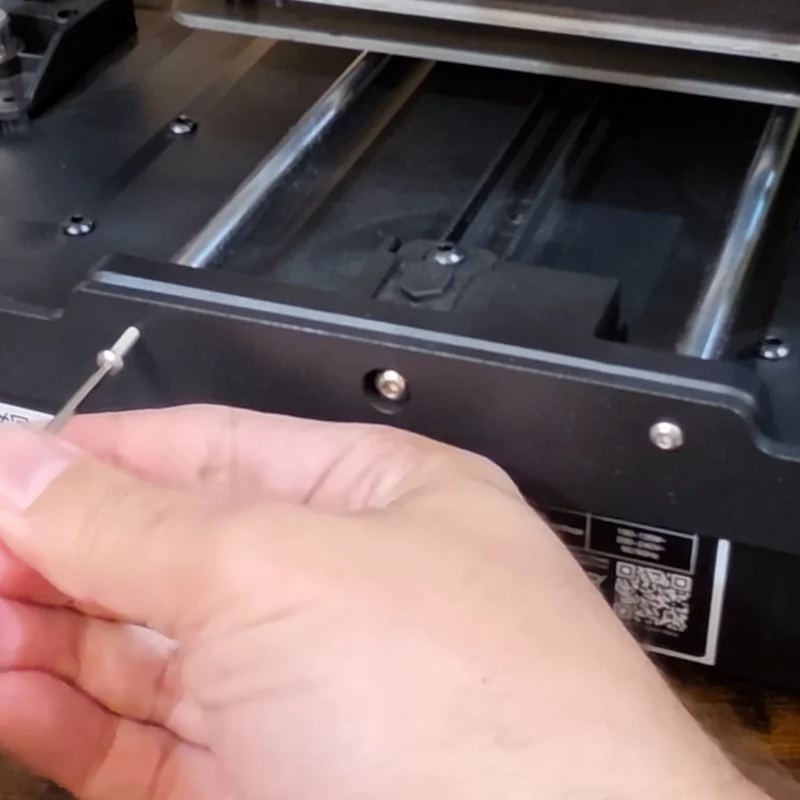
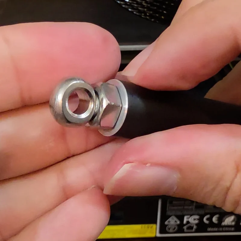
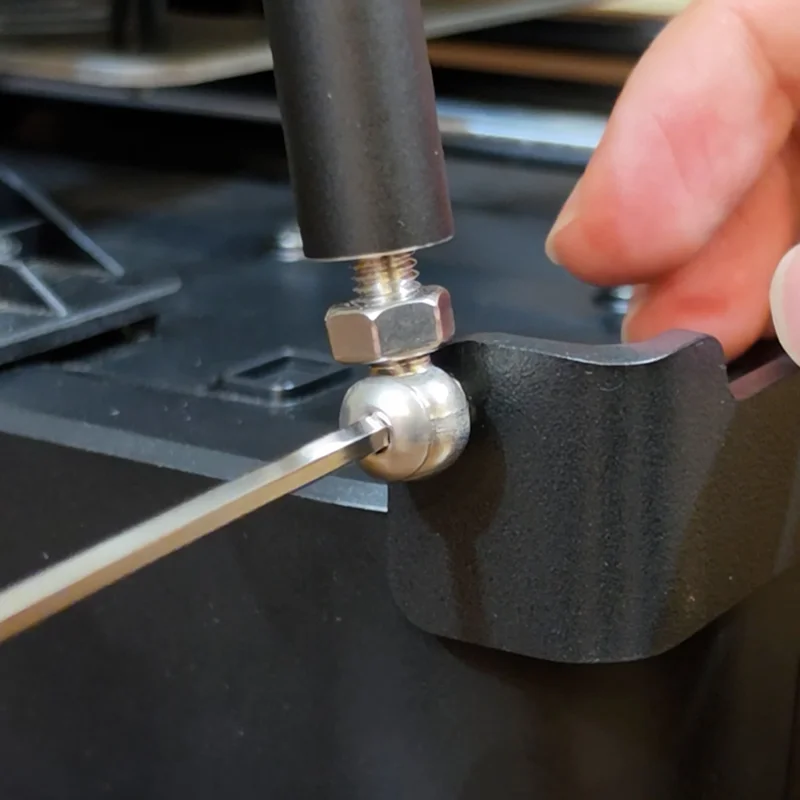
Place a nut and an eye bolt on each end of the aluminum rods, but do not tighten them completely yet. Connect the rods to the top brackets first using the M5 screws. To align the bottom eye bolts with the bottom bracket, simply spin the rod or the eye bolt to extend or retract the length. Make equal movements on both rods to keep the frame square, then insert the final screws and use the included wrench to tighten the nuts. Because the kit installs on the back of the frame, the front of the printer stays completely clean and open.
Crucial tip: The pre-drilled holes in the top and bottom brackets are incredibly tight. Save yourself some frustration by pre-driving the M5x12mm screws into the rod holes by themselves first, to clean the threads before final assembly.
While the support rods vastly improved the frame's rigidity, they created a new problem: they blocked the exact spot where my custom side-mounted spool holder used to live.
On top of that, Version 1 of my side-mount mod used a hook that went under the printer's rubber foot. Feedback from the community made it clear this was inconsistent, since rubber-foot heights vary between printers. Sometimes the mod was left dangling, and sometimes it lifted the printer off the table entirely.
I went back to the drawing board to turn the support rod from an obstacle into an advantage. The new SR1, short for Support Rod, ditches the under-foot hook and instead snaps directly onto the new aluminum support rod itself, giving it a solid anchor that keeps the mod from tilting forward. I also added an extension that fits perfectly into the cavity created by the new YOOPAI bottom brace. This secondary anchor prevents the weight of a full 1kg spool from twisting or sagging the holder.
It is a tight fit and takes some force to seat all the way down, but once installed it is incredibly rigid. You can now pick up and move the entire printer without the mod falling away. The model prints on its side in about 1.5 hours and needs absolutely no supports.

Since the top of the gantry now carries those new steel plates, I redesigned the filament guide to hook directly onto their open edge. Because the plates are steel, the new guide includes a slot for a 40mm bar magnet, which makes the fit feel deliberate and secure.
The files include both a roller version and a simple loop version. Both take less than 15 minutes to print, and neither needs supports.
After installing the support rods and the new SR1 spool holder, I ran the high-speed stress test again. The results were pristine. No wavy lines, no swaying, just a smooth, stable flow even at the top of the Z-height.
Mounting the spool on the side also gives the filament a bit of slack, which stops it from constantly tugging on the spool and causing further vibrations during rapid jerking motions.
No wavy lines, no swaying, just a smooth, stable flow.
Since YOOPAI has officially discontinued their hardware, I want to hear from you. Should I design my own custom support rod kit? I am considering a fully 3D-printed version that uses basic, inexpensive hardware you can pick up at any local hardware store. I posted a poll over on the YouTube channel, so head over there to cast your vote, or drop a comment below to let me know if this is a project you want to see. In the meantime, stay tuned for the next project, where we install the Creality filament run-out sensor to see if we can make it play nice with this side-mounted setup.
The side-mount spool holder is a custom 3D-printed holder designed specifically for the Ender 3 V3 SE. It relocates the spool from the top of the printer to the side, reducing vibration and improving stability during prints.
Mounting the spool on the side helps reduce wobble and sympathetic vibrations that can affect print quality. It also lowers the center of gravity and makes filament feeding more consistent, especially at higher print speeds.
It was custom designed for the Ender 3 V3 SE. The SR1 version anchors onto the YOOPAI support rod and its bottom brace, so it will not fit other models without modification.
An infill of 20% is strong enough for both parts, and no supports are needed. Print the spool holder flat with no brim or skirt, since it barely fits on the Ender 3 V3 SE bed. PLA, PETG, or a stronger filament like ABS all work well.