A nice upgrade from the MS V2, assembly is straightforward
Full Product Name
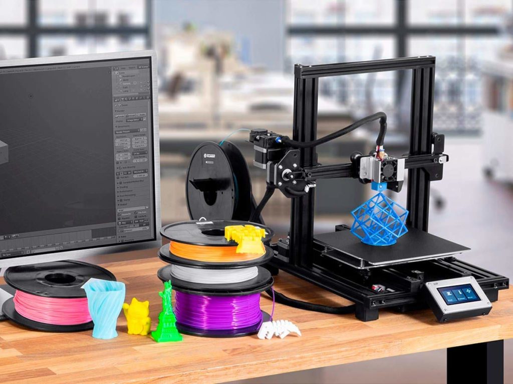
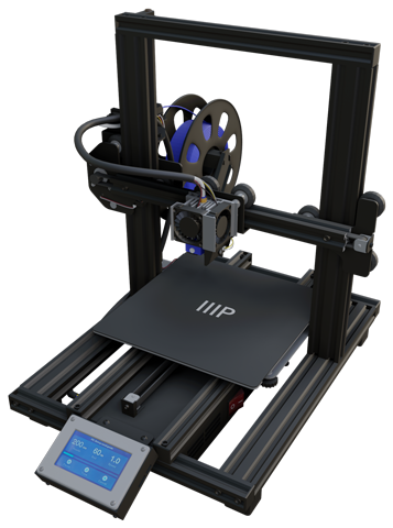
Monoprice-134438 MP10 Mini 3D Printer – Black with (200 x 200 mm) Magnetic Heated Build Plate
Intro
It’s been a while since I made 3D printing video. Part of the reason for that is because I thought my Maker Select V2 was out of commission for good but I recently discovered a fix, although it may only be temporary. More on that in another article.
Full Review
Watch the overview video or keep reading the full article below

Table of Contents
Purchase Choice
When the V2 broke down I started looking for a replacement. I decided to stay within the Monoprice ecosystem since I was familiar with how they operate. That being said I still had some criteria I wanted to follow for the newer printer. First I realized I’ve never utilized all of the print bed for any project so the bed size wasn’t as big a factor as when I chose the V2. Also, a smaller bed makes it easier to level and keep level. Speaking of which I wanted a printer that was easier to again level the bed and keep it leveled, maybe an auto-leveling feature? Next, I wanted the printer to be faster, the 70mm/s of the V2 is fine but some prints feel like they take forever! Following that a more compact design would really help with the limited space I have. Lastly price, I still don’t feel like investing $1000 into a top-tier printer just yet. I want to get a new computer first!
Even though I told myself I’ll stick with Monoprice, I was still curious to see what’s out there. Looking through the ever-growing list of budget printers it’s interesting to see just how many more are available now since I bought my V2. Nevertheless, a few models from different manufactures met the criteria I was looking for but in the end, I still stuck to Monoprice and got their Maker Plus 10 Mini also called just MP10. It ticks all the boxes and at $270 it felt like a no-brainer to try out.
MP10 Mini Specifications
A quick overview of the specs, the bed size is identical to the V2 at 200 by 200 by 180 millimeters or 7.87 by 7.87 by 7inches, it’s only considered a Mini because the full-sized MP10’s print area is more than twice as tall and a bit wider. The printer speed maxes out at 100mm/s which is almost 43% faster than the V2, so a nice bump there! Printing resolution gets a bump as well, while the V2 ranged between 100 and 400 microns the MP10 brings it down to between 50 and 300 microns. Lastly, the extruder can reach temps of 280C or 536F again an improvement over the V2’s 240C or 464F.
In this article we’ll focus on the assembly of the MP10, then in part 2 we’ll fire it up and see how good this printer is out of the box, so make sure you’re subscribed so you don’t miss out on that!
It’ll be interesting to compare the assembly processes between the V2 and MP10 Mini. Right off the bat, the box for the MP10 is almost half the size of the one for the V2 odeing to its more compact size. Pulling out the contents of the box we find the printer in two main pieces sandwiched between styrofoam cradles. Along with some included filament, the instruction manual, and a support brochure.
What’s Included
Before we pop out the body of the printer we have an accessories box tucking into a pocket built into the styrofoam holders. In here we first find a really short power cable, then a type b USB data cable and a 16gb micro-SD card, then some replacement parts of the extruder, a bag of assorted screws for assembly, a bag of assorted Allen keys, and a wrench, the two pieces that make up the spool holder, and lastly a plastic scraper. Nothing out of the ordinary here.
Let’s crack this egg! We have two main pieces to assemble just like with the V2, the base and the vertical frame. Unlike the V2 there is no separate power supply slash control unit. It’s all incorporated into the base which saves a tonne of room and makes moving the printer around much easier, but as we’ll see later this layout does have some drawbacks.
Before we start the assembly process there was one more piece hidden in the styrofoam cradle, the touch screen monitor. We’ll put that aside for now.
Assembly Instructions
Step One – Remove shipping brase
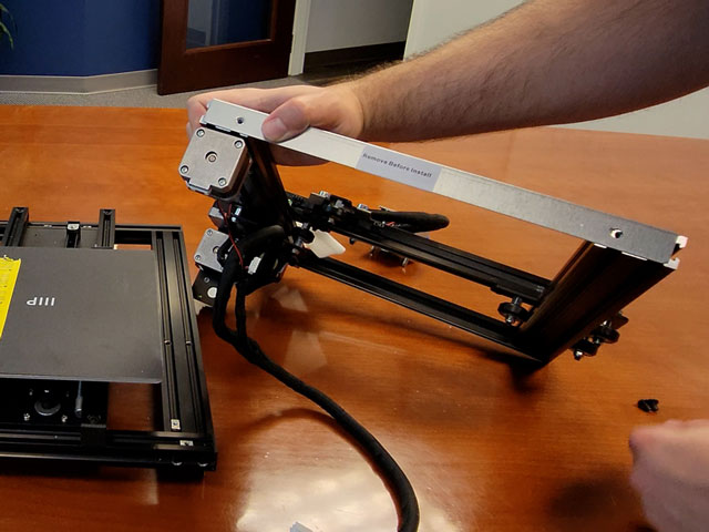
We definitely need to talk about the included instructions. While they are clear and succinct, they are missing a few steps and by a few I mean a lot. The very first thing you need to do that’s not in the instructions is to remove this temporary brase on the bottom of the vertical frame using the 2.5mm allen key. I believe it’s there to protect the frame and gantry during shipping.
Step Two – Attach vertical frame
Next we’ll attach the vertical frame to the base using the M5 screws. I found it’s easiest to put the base on it’s side and slide the frame in place while you screw it in. These screws need the 4mm allen key. One thing to be aware of is that for some reason they didn’t secure anything in place so the bed and print head are going to slide around, so just be careful as you tip the base and vertical frame over. On the V2 anything that could move was zip tied in place, something that definitely was missed here.
Secure the frame in place and put it back on its feet. Speaking of the feet they are super sticky, even on this smooth table this thing will not move, good marks there.
Step Three – Remove screw rod
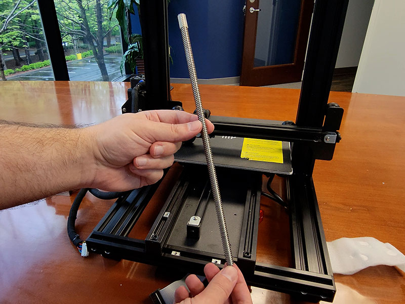
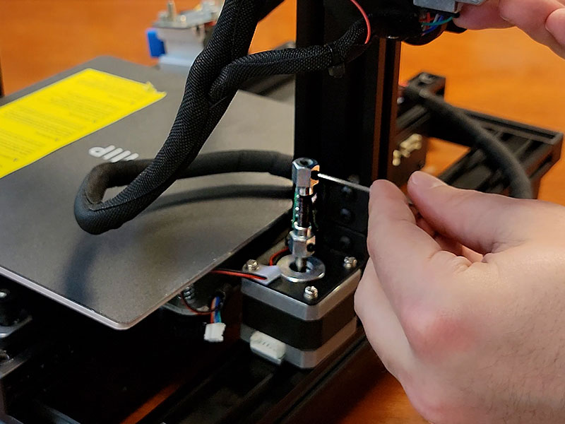
Another major departure from the V2 is the single screw rod for the gantry. The rod itself is secured under the bed by these two temporary brackets. Just loosen them with the 2.5mm allen key and the rod will drop down. Make sure to completely remove those brackets as they will interfere with the operation of the bed. Another word of warning, the screw rod is covered in grease so you’ll either want to wear gloves or use something to keep your fingers from getting greasy, but remember this thing needs to be greased up to run smoothly. It would have been really nice if they mentioned this in the instructions.
Step Five – Install screw rod
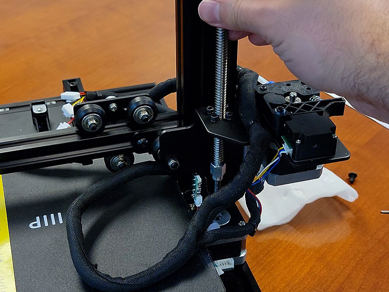
From the top frame slide the rob down the shaft into the rob holder. Twist the rod into place making sure it slots into the cradle at the bottom. Twist until the horizontal gantry starts to move upwards, keep twisting until the gantry motors clear the set screw on the rob assembly. Now you can fasten the set screw back in place.
Step Six – Attach screen
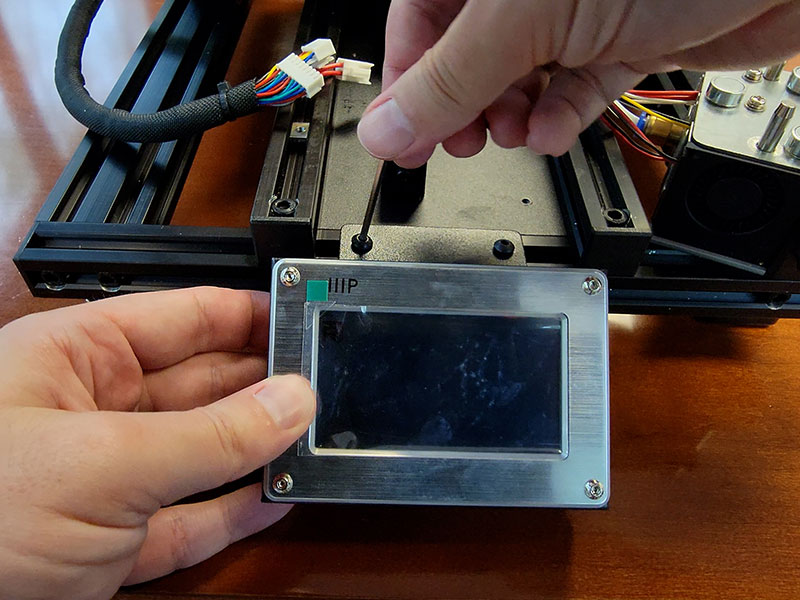
Next up we’re going to attach the screen. Flip the screen face down and plug in the data ribbon into the port on the underside, there’s a notch on the connector to make sure it only goes in the way it’s supposed to. Flip it back over and use the M4 screws and the 2.5mm allen key to attach it to the front frame of the printer. Just be aware that these screw mounts slide inside the frame making aligning the bracket and screws a little tricky, so just be patient with it. With the screen secured let’s do a nice slow peel.
Step Seven – Attach print head
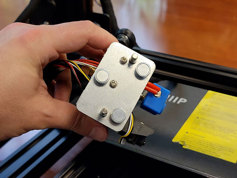
You may have noticed by now the print head assembly looks quite a bit different from the V2 not only in it’s design but also how it attaches to the frame. No screws, the whole assembly magnetically attaches directly to the gantry support. There are three strong magnets and two posts that help line it up. Once it’s in place it does not move without some significant persuasion. I love how easy it is to remove, now you have no excuse for not keeping the nozzle clean.
Step Eight – Install spool holder
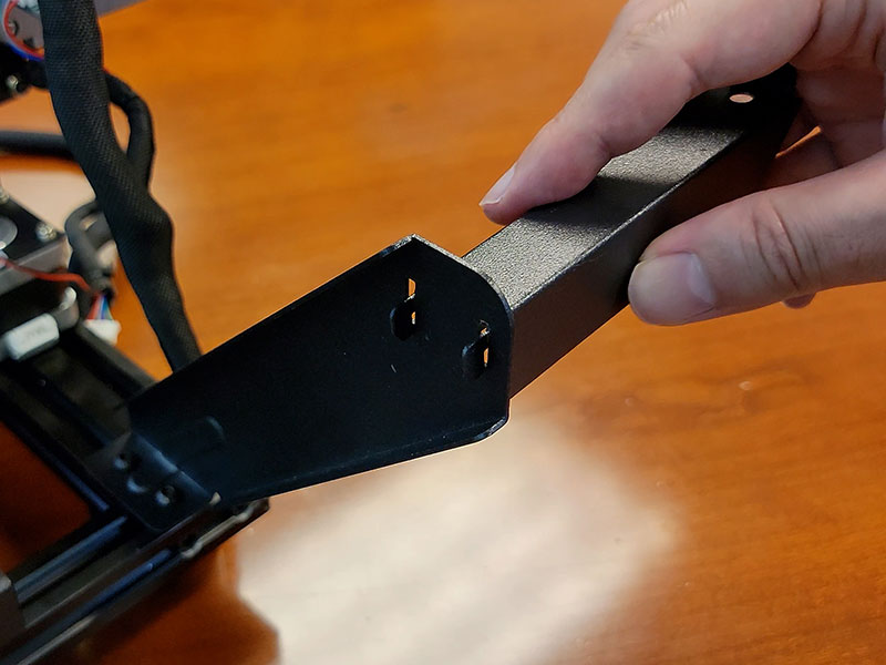
The last thing we need to screw in is the spool holder. As you probably have guessed unlike the V2 we attach the spool holder directly to the base in the back left corner. Like when attaching the screen you attach the vertical brase to these mounts and again they move around as well so just try to line them up without punching the thing. We’re using the M4 screws and the 2.5mm allen key. This and the screen mounts could have been implemented a little better. Anyway after securing that the horizontal piece slots into these cut outs and hangs in place.
I have a feeling my smooth spool holder mod will help here since this holder is extremely basic. If you didn’t see the article where I created and tested that mod you can read the Smooth Spool Holder Mod. In part 2 we’ll see how the MP10’s method of feeding the filament is a bit of a departure from the V2.
Step Nine – Plug in cables
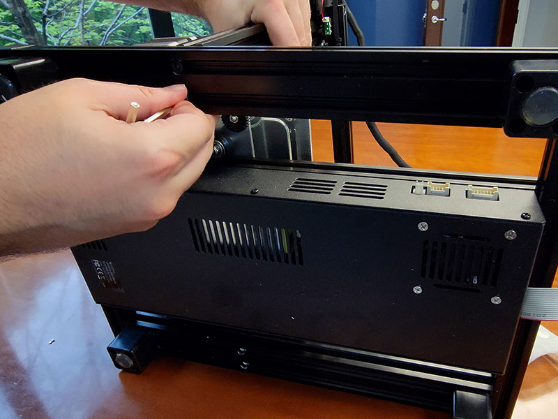
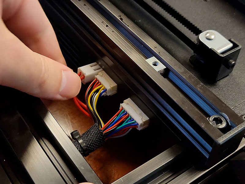
Let’s plug in some more cables. This is where having the PSU incorporated into the base becomes a little tricky but since you’ll only be doing this step once it’s fine. Unlike with the V2 where you had to plugin the data/power cables into each motor, that’s already done here. You only need to plug in the main three plugs into their respective ports on the side of the PSU. Each one is uniquely shaped so you can’t put them in the wrong port. It does feel like you need small hands to maneuver in this tight space.
Step Ten – Plug in A/C power
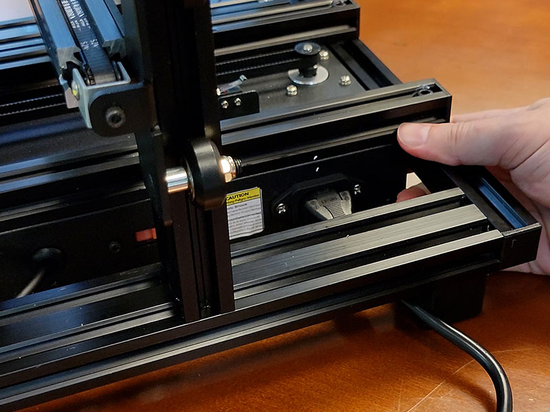
We have one more thing to plugin. Unfortunately, we have another cramped space in the back corner of the PSU to try and plug in our AC power. With enough finesse, you can get it slotted in. Again I don’t understand why this power cable is so short, it doesn’t even make it to the bottom of the table to plugin.
Wrap Up
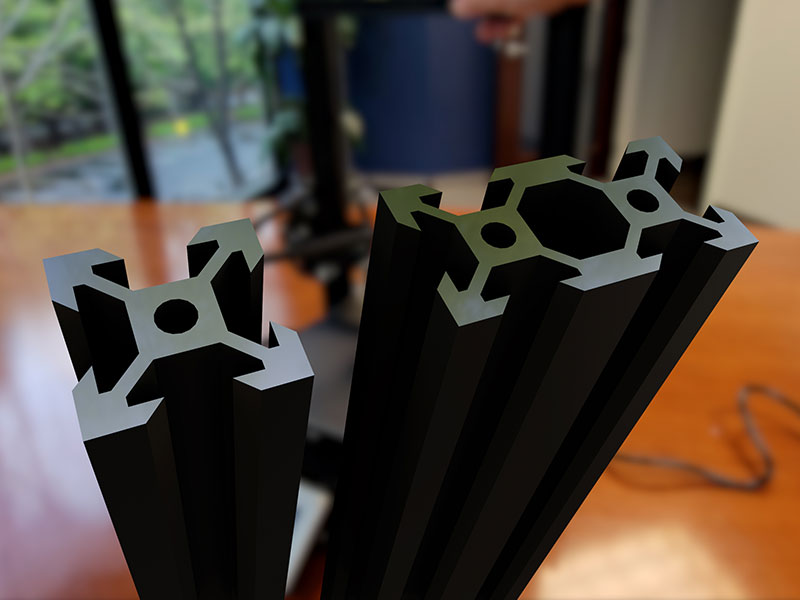
Now we are done with assembly! Putting the MP10 together felt a little more straight forward and simpler than the V2. I’m not sure if that’s because it really was or if my past experience helped make this assembly smoother. Nevertheless, out of the box this printer feels more solid than the V2 when it comes to the flex of the vertical frame. I think that’s due to the shape of the truccess that make up the frame. This shape gives the frame inherent strength and resistance to flexing unlike the flatter folded pieces that makeup the frame of the V2.
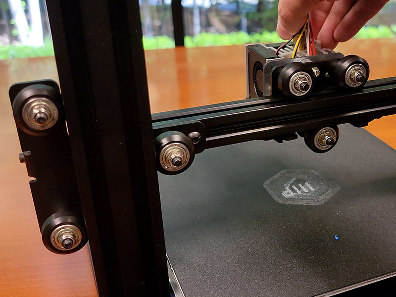
One other thing that may have caught your attention as it did mine is the use of rollers to guide different parts of the printer. There are 13 of these wheels strategically placed to insure smooth operation. I think I prefer this approach over the gliding set up of the V2. If you don’t keep the surface clean and the grommets lubed, those glides will slowly stop well gliding. The likelihood of these wheels sticking is much lower but again there are 13 of them and if even one starts acting up it could adversely affect a print. But unlike the gliding design it’s extremely easy to swap out one of these rollers.
Maker Pro 10 Mini User Manual - PDF
In-depth user manual that covers all most everything from un-packing and setup to 3D slicing program settings and fan speed configuration. Please read before using this printer.
Conclusion
In part 2 we’ll fire this thing up and start checking out some of the features that pushed me to get this printer, like auto leveling and intraprinting bed adjustments, then we’ll print a few models to see how they turn out, and compare them to the prints from the V2.
- EXCEPTIONAL PRINT QUALITY: Achieve high-resolution prints with a precision nozzle that ensures detailed and smooth models with printing accuracy up to ±0.1mm, ideal for prototyping and sample creation.


