Intro
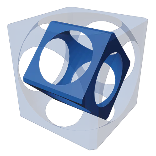
I’d like to think this episode will be part creative experiment, part tutorial. I’m going to go over how I went from conception to creation of this. It’s basically four concentric cubes inset into each other to create this cool geometric object, a little cubeseption. I learned a lot in trying to model this thing to make it possible to 3D print, so I hope you appreciate the journey and learn something to help in your 3D printing projects!
Full Review
Watch the overview video or keep reading the full article below
Table of Contents

Let’s jump right into it. The individual cubes themselves are actually straight forward to model and their design directly contributes to making them easy to 3D print. In Blender we can actually use the starter cube for once. Add a sphere, scale it so that it protrudes from the cube but doesn’t engulf it. Add a Boolean modifier to the Cube, with the difference option select the sphere as the Object target. This modifier cuts the shape of the sphere out of the cube. Next apply the modifier and delete the original sphere. Now we have a cube with a sphere cut out of it. This will serve as the outermost cube of our model.
3D Printing Supports
The benefit of this design, besides just looking cool, is that it can be printed without any additional programmed supports. In case you’re not familiar with supports in 3D printing, they are used when a design has an overhang that is not supported from below. Programmed supports are automatically added in slicing programs like Cura with this option and are identifiable by this turquoise color.
You can tell where the program will add supports by looking for the red-shaded areas on the underside of your design in the model view. Cura believes these areas can not be printed without supports but we know better.
Supports are meant to be printed in such a way that it uses the least amount of material to support the model and is only superficially attached so that it can be easily removed after the print is done.
While these supports are very helpful in printing interesting shapes it can create some issues. While they are designed to be removed easily they can still leave a lot of leftovers. With intricate models these remnants can be detrimental to remove and if you’re not careful you can break the finished print. They can also be incredibly difficult to remove from a model with open interior spaces kind of like our design.
Model Goals
So the goal is to setup this model in such a way that programmed supports would not be required. The physics of most printers dictates that any flat surface can’t exceed roughly 70 degrees without needing supports underneath. The beautiful thing about the way this is modelled is that the spherical space on the inside of the cubes are essentially arches. The beautiful thing about arches and 3D printing, just like in civil engineering, is that you can span considerable distances during the build process without additional support.
This can be done because each layer of an arch prints just a fraction of millimeter further in from the previous layer so that it’s still held up from below and can creep inward with each layer until the arch is connected.
This accounts for printing the cube itself. Now how do we inset the other cubes so that they all can be printed at the same time? Let’s step through how I set up the three interior cubes and finish up this design.
Interior Cubes
First Interior cube
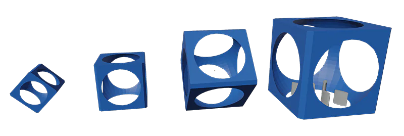
I wanted each of the interior cubes to be small enough to move around freely but large enough so that it doesn’t fall out of the parent cube. To accomplish this for the first interior cube I simply copy and pasted the original one then scaled it down 15% again just enough to allow it to move freely and stay inside the parent cube.
Simply leaving it to sit on the inside of the parent cube will not work, so what can we do here? With this cube I found a pretty easy solution which just involved rotating it 45 degrees on the y axis thus printing it on its edge directly on the print bed. Since none of the faces hang more than 50 degrees and with the inherent benefits of the design that we already discussed there’s no need for additional supports.
There was one caveat, I did end up beveling the four corresponding edges so that there was a flat surface to print the cube on. I went ahead and beveled all the cubes to keep the design consistent.
Figuring out how to orient that cube was fairly straight forward but the next one was going to be a little more of a challenge.
Second Interior cube
The third cube was again another scaled down copy, free to move but firmly inside the second cube. This cube is basically floating in mid air. No part of it could touch the bed of the printer, so how can we print this cube where it is? I tackled with this problem for some time when I realized there was just enough room to create my own custom supports underneath to facilitate the printing of this cube. The challenge is how to add those custom supports so that it’s enough to hold up the printing process and light enough to be removed easily after the print is done.
The trick is to support the corners since these are points that print head will travel to and from. From here we can take advantage of a 3D printing characteristic called bridging. Basically this is the ability to connect two points without supports in the middle. This can be done because as the printer extrudes filament in mid air while moving to the next point it basically pulls the filament along with it and thus can bridge a gap.
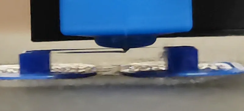
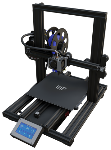
Of course, this is highly dependent on the printer’s capabilities. I ran a couple of bridging tests to see how large a distance the V2 and MP10 can bridge before sagging too far. I found the V2 can bridge roughly 60mm without a problem, the MP10 can do the same. With that said we just need to support the area from the outer corner to the edge of the interior at roughly 45 degrees to the center, which led me to a simple oblong oval shape that again will hold up the corners and will support the cube as it prints and allow for easy removal.
Naturally, I did have to make sure this was the case with a test print of this cube alone. Here it is, our cube on custom supports, a very promising result and barely any sagging while bridging all four sides.
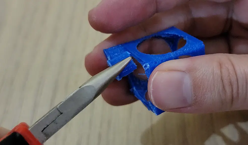
With this print we get a bonus test to see how easy breaking off the supports we added will be. From this test it looks like it’s going to be fairly easy.
Third Interior Cube
Lastly the fourth cube was another interesting challenge but all I had to do was look at the second cube for inspiration. I could put this cube to print on its edge as well. This time though It would need it’s own custom supports. Luckily all I had to do was look at what I did with the third cube. Putting the fourth on it’s edge and adding two more supports not only allows the fourth cube to be printed but also gives the third cube additional support which as we just demonstrated isn’t needed but it won’t hurt.
I printed the fourth cube on it’s own to confirm the theory, again another promising result. Not clean but we can work that. It’s the physics that I was more concerned about.
Here we have the final CAD model. We can see each cube individually, then all together. Ready to be exported.
After importing into Cura I scaled the modal to 50mm across. I found this size to be optimal, It’s large enough that all the cubes come out mostly clean but small enough that bridging the third cube like we mentioned earlier shouldn’t be an issue. I set the infil to 100% to basically make a solid object which also adds rigidity to the smaller cubes, of course this does add to the build time. I tried lower infil percentages but the smaller cubes ended up more fragile than I’d like so 100% was the way to go.
There are plenty of other tweaks we can make with the printer settings like retraction speed, distance, wall thickness etc but it’s best to leave everything as is and tweak the settings to suit your printer based on your results.
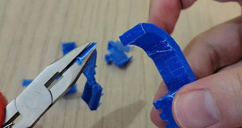
Here we are. Removing the adhesion layer and breaking off the supports does take a little finesse. You definitely want to gently hold the third cube while removing the supports. I found that if you bend them side to side just a little and then twist they break off easily and cleanly. Needle nose pliers work best here but scissors will do in a pinch.
Conclusion
A cleaned up model is fun to mess with and makes for an interesting desk piece. I feel like this would make for a good stress test for any printer. Much like the Benchy we printed in previous episodes it tests quite a few areas of the printer’s capabilities. My results definitely could use some more work, I won’t deny that. I’ll explore some of those improvements in future videos.
I’ll provide the Blender and STL file on Thingiverse. Download them and give it a try yourself! I’d be curious to see how these turn out for you all!


