After years on the Maker Select V2, I moved to the compact MP10 Mini: faster, hotter, and easier to level. Part 1 covers unboxing and the full build. Part 2 fires it up and tests it against the V2.
Editor's note (July 2026): This review is from 2021, and the MP10 Mini is discontinued now. It was a solid step up from the Maker Select V2 at the time. If you are shopping for a beginner printer today, I use and recommend the Creality Ender 3 V3 SE, which has full automatic bed leveling and assembles even faster. See the link at the end.
The MP10 Mini was a genuine upgrade from the V2 at about $270: the same 200 by 200mm bed, but faster at 100mm/s, a hotter 280 degree C hotend, finer resolution, and assisted leveling. Assembly is two main pieces and felt simpler than the V2, with a much more rigid frame. The catch is the included instructions, which are clear but skip a lot of important steps. This part covers the full build. Part 2 tests it.
A compact, more rigid step up from the Maker Select V2.When the V2 broke down I went looking for a replacement, and I decided to stay in the Monoprice ecosystem since I knew how they operate. I still had a checklist, though. I had never used the full print bed on any project, so bed size was not a priority, and a smaller bed is easier to level and keep level. Leveling was the big one: I wanted something easier to level, ideally with an auto-leveling feature. I also wanted more speed, since the V2's 70mm/s made some prints feel like they took forever, and a more compact design to fit my limited space. Last was price. I was not ready to sink a thousand dollars into a top-tier machine yet, since I want a new computer first.
Even set on Monoprice, I looked around, and it is striking how many budget printers exist now compared to when I bought the V2. A few models from other makers met my criteria, but in the end I stuck with Monoprice and got their Maker Pro 10 Mini, also just called the MP10. It ticked every box, and at $270 it was a no-brainer to try.
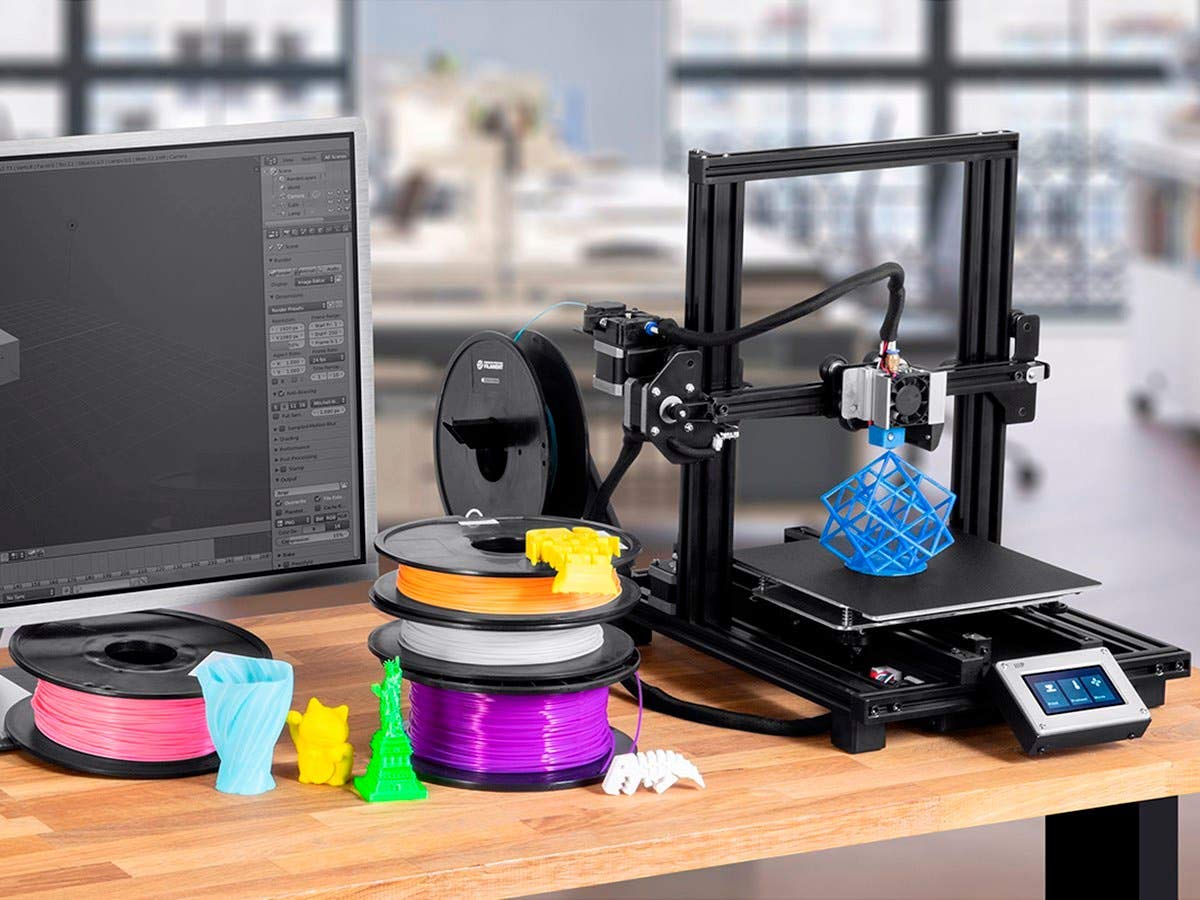
The bed is identical to the V2 at 200 by 200 by 180mm (7.87 by 7.87 by 7 inches). It is only a Mini because the full-size MP10's print area is more than twice as tall and a bit wider. Everywhere else it pulls ahead of the V2, as the headline numbers show:
| Print area | 200 x 200 x 180 mm (7.87 x 7.87 x 7 in) |
|---|---|
| Print resolution | 50 to 300 microns |
| Print speed | Up to 100 mm/s |
| Max extruder temp | 280 degrees C (536 degrees F) |
| Bed leveling | Assisted |
| Supported filament | PLA, ABS, PETG, Nylon, Wood fill, Metal fill |
| Price at launch | About $270 |
This part focuses on assembling the MP10. In part 2 we fire it up and see how good it is out of the box, so subscribe if you do not want to miss that.
It is interesting to compare the two unboxings. The MP10's box is almost half the size of the V2's, thanks to its more compact design. Inside, the printer sits in two main pieces cradled in styrofoam, along with some starter filament, the manual, and a support brochure. Tucked into a pocket in the styrofoam is the accessories box, which holds:
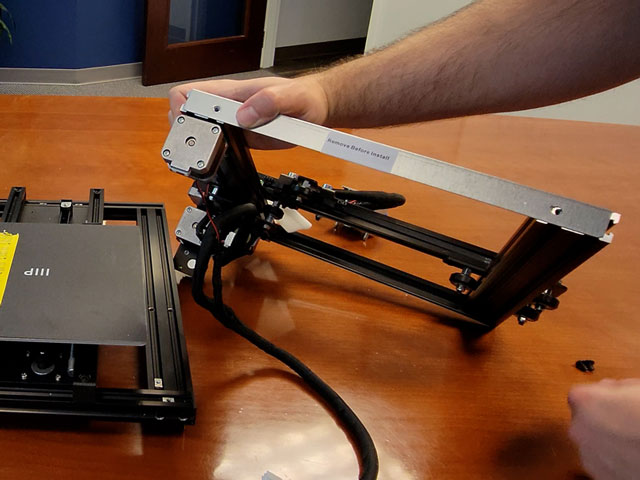
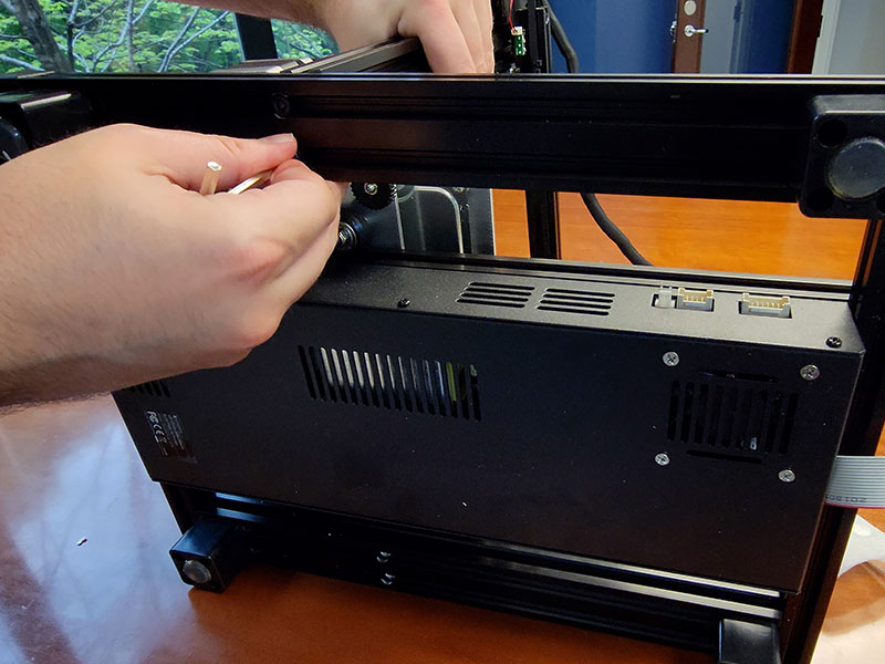
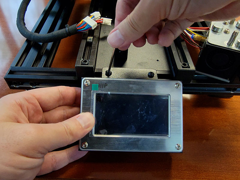
Nothing out of the ordinary. The two main pieces are the base and the vertical frame, just like the V2. The big change: there is no separate power-supply-and-control unit. It is all built into the base, which saves a lot of room and makes the printer much easier to move, though as we will see, that layout has some drawbacks. One more piece hides in the cradle, the touchscreen monitor, which we set aside for now.
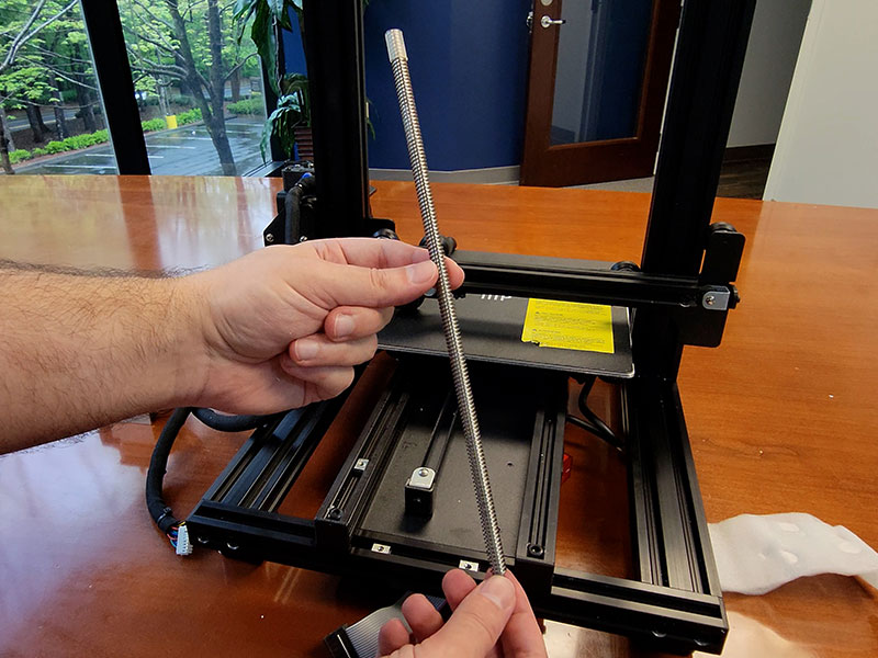
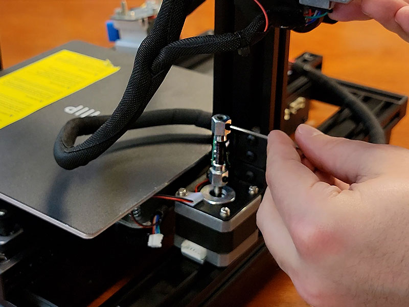
We need to talk about the instructions. They are clear and succinct, but they are missing more than a few steps. Here is the full sequence, including the parts the manual leaves out:
The spool holder is very basic. I have a feeling my smooth spool holder mod from the V2 series will help here. In part 2 you will see the MP10's filament feed is a bit of a departure from the V2.
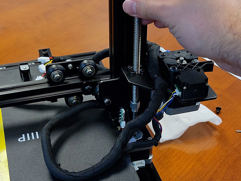
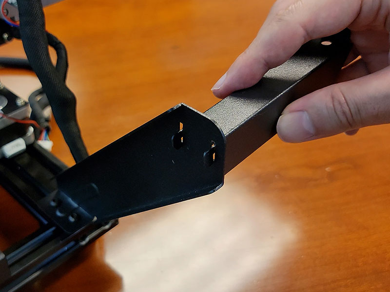
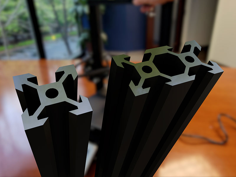
Assembly done, and it felt more straightforward and simpler than the V2. I am not sure if it truly was, or if my past experience just smoothed it out. Either way, out of the box the MP10 feels more solid than the V2, with much less flex in the vertical frame. That is down to the truss shape of the frame pieces, which gives them inherent strength against flexing, unlike the flatter folded pieces on the V2.
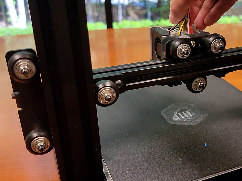
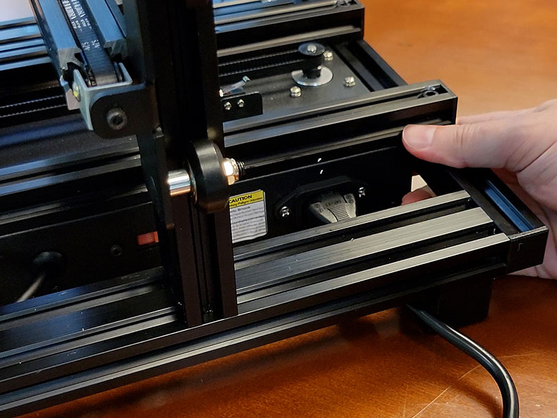
The other thing that caught my eye is the use of rollers to guide the moving parts. There are 13 of these wheels placed to keep motion smooth. I think I prefer this to the V2's gliding setup, where the rails slowly stop gliding if you do not keep the surface clean and the grommets lubed. These wheels are far less likely to stick, and even though there are 13 of them, if one starts acting up it is extremely easy to swap out, unlike the glides.
Monoprice also provides a thorough user manual that covers everything from unpacking and setup to slicer settings and fan configuration. It is worth reading before you print. You can grab the Maker Pro 10 Mini user manual PDF here.
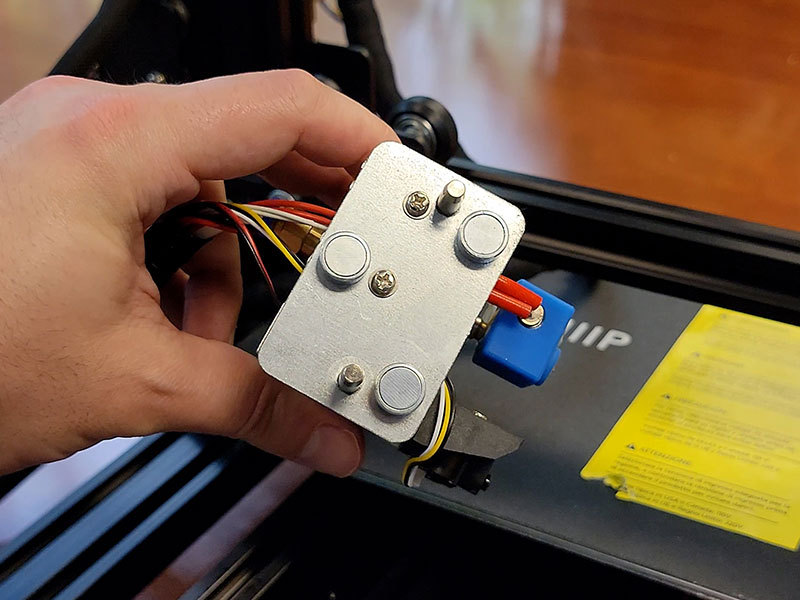
Yes. It keeps the same 200 by 200mm bed but adds real improvements: about 43 percent faster printing at 100mm/s, a hotter 280 degree C hotend, finer resolution down to 50 microns, assisted leveling, a magnetic print head, and a noticeably more rigid frame. At around $270 it was an easy step up.
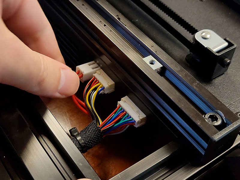
It is two main pieces and felt simpler than the V2. The catch is the included instructions, which are clear but skip several important steps, including removing a shipping brace, greasing the screw rod, and freeing the temporary bed brackets. Follow a full step-by-step and the build is straightforward.
The MP10 Mini has a 200 by 200 by 180mm build volume, which is 7.87 by 7.87 by 7 inches. The bed footprint matches the Maker Select V2. The only real difference from the full-size MP10 is height, since the full MP10 is more than twice as tall.
It has assisted leveling rather than fully automatic leveling. That is easier than the fully manual leveling on the V2. I cover the leveling and the in-print bed adjustments in more detail in part 2, where the printer is actually fired up.
The MP10 uses a trussed frame that resists flexing far better than the V2's flatter folded metal, so it feels more solid out of the box. It also rides on 13 guide rollers instead of sliding rails, which are less likely to stick and much easier to replace if one wears out.
That is the MP10 Mini assembled and ready. In part 2 I fire it up and dig into the features that pushed me to buy it, like assisted leveling and in-print bed adjustments, then print a few models and compare the results to prints from the V2. This printer became my go-to for the new Blender-to-Cura workflow, and it stood in for the whole Maker Select V2 journey that came before it.
Disclosure: This post contains affiliate links. As an Amazon Associate I earn from qualifying purchases, at no extra cost to you. CK Tech Check is 100% ad-free: no banner ads, no ad tracking. Affiliate links like these and my YouTube channel are what keep the site running.