Layering several images, including transparent ones, on a single face is fiddly in SketchUp and elegant in Blender. This is your first real taste of the shader node system, and it is worth it.

Editor's note (July 2026): Written for Blender 2.8. The node workflow is unchanged with one important rename: the MixRGB node used throughout was replaced by a unified Mix node in Blender 3.4, and it is the standard in 4.x and 5.x. Add it with Shift+A then Color then Mix Color. Its sockets were renamed too: the old Fac, Color1, and Color2 are now Factor, A, and B. So wherever this guide says connect to Color2 or Fac (matching the screenshots), use B or Factor on the current Mix (Color) node. The Image Texture, Texture Coordinate, and Mapping nodes and how they connect are exactly the same. New here? Start at Part 1; this follows Part 6.
Open the Shader Editor and you will see two nodes: Principled BSDF and Material Output. To stack images on one face, drag each image in to make an Image Texture node, feed a transparent image's Alpha into a Mix node's factor so it blends over the one below, and chain a Mix node per extra image. Texture Coordinate and Mapping nodes let you position each image independently. Four images take just four node types.
Four node types, unlimited image layers.Everything so far has used one node without you really seeing it. The node system is where Blender's materials get powerful, and this lesson does something impossible in SketchUp: layering several images on a single face. Open the Shader Editor by switching the lower pane's editor type to it. You will see two nodes already there: the Principled BSDF you have met, and the Material Output, which is where Blender sends the finished material, usually the last connection in any setup.
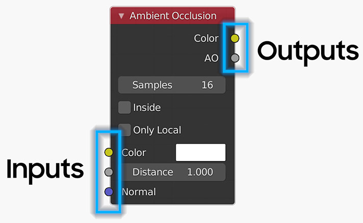
Nodes follow one simple rule: inputs are on the left, outputs on the right, and you connect an output to an input. One output can feed many inputs, but an input generally takes just one connection. Add nodes the same way you add objects, with Shift+A, which opens a menu of nearly ninety node types. You can drag nodes around and collapse them, which you will want to, because these setups get elaborate and start to look like spaghetti and meatballs.
Add a fresh cube (it comes pre-unwrapped, so no UV prep) and create a new material. In the Shader Editor, drag and drop a transparent PNG straight onto the workspace: Blender makes an Image Texture node with your image loaded. Set its Repeat option to Clip so you see just one copy. Delete the Principled BSDF node (select it and press X), then add a MixRGB node with Shift+A then Color, and drop it between the image and the Material Output.
Now wire it up:
Switch to Material Preview and there it is: your transparent image sitting over a solid background color you control, with the UV editor still available to reposition it.

To layer a second image, first tidy the first one. Drag the first image's connection from Color2 to Color1, and remove its Alpha-to-Fac link by dragging it off into empty space (so it becomes your solid base layer). Now drag in a second image, set Repeat to Clip, and connect its Alpha to the MixRGB Fac and its Color to Color2, so it blends on top.
Here is the important addition for placing images independently. Add two more nodes, a Texture Coordinate and a Mapping node, and connect them:
With those in place, use the Mapping node to set each image's position, rotation, and scale, rather than the UV editor. That is what keeps two graphics correctly placed on the same face without one shoving the other around.

From here it is just repetition. Duplicate the second-image setup for each new layer, and chain the Mix nodes together: connect the first MixRGB's output into the new MixRGB's Color1, route the next image's Alpha to that node's Fac and its Color to Color2, and send the new MixRGB's output on to the next one. The very last MixRGB in the chain connects to the Material Output's Surface.
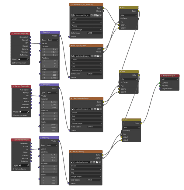
That pattern stacks as far as you want: previous Mix output into Color1, new image on Color2 keyed by its Alpha, final Mix to the output. You can rearrange nodes and swap connections any time to change the layering order, positions, and orientation. My four-image setup uses fourteen nodes, but only four node types: Image Texture, Texture Coordinate, Mapping, and MixRGB. Position them however you like, as long as the connections stay consistent.

Tidy the spaghetti. By default node connections are straight lines. Under Edit → Preferences → Themes → Node Editor, raise the Noodle Curving value from 0 to curve them. Higher is curvier. I like it set to 4.
Use the Shader Editor. Add an Image Texture node per image, then chain Mix nodes: each new image's Color goes into a Mix node keyed by its Alpha, blended over the layer below. Texture Coordinate and Mapping nodes place each image independently.
Switch the lower pane's editor type to Shader Editor. You will see the Principled BSDF and Material Output nodes by default. Add more nodes with Shift + A, connecting outputs on the right to inputs on the left.
Drag the PNG into the Shader Editor to make an Image Texture node, set Repeat to Clip, then connect its Alpha output to a Mix node's factor. The alpha channel controls where the image shows over the layer beneath it.
They control where an image sits on a face. Connect Texture Coordinate's UV output to the Mapping node's Vector input, then Mapping's Vector output to the Image Texture's Vector input. The Mapping node then sets that image's position, rotation, and scale.
It was replaced by a unified Mix node in Blender 3.4. Add it with Shift + A, Color, Mix Color. Its sockets were renamed from Fac, Color1, and Color2 to Factor, A, and B, but it works the same way as the MixRGB shown here.
Fourteen nodes for four images sounds like a lot, but it is the same four building blocks repeated, and once the pattern clicks you can layer as many images as you like. More importantly, you have now used the node system, which is the doorway to everything advanced in Blender materials.
The series keeps going with more Blender techniques, including a handy one I use constantly: seeing through objects in the viewport while you work.
Disclosure: This post contains affiliate links. As an Amazon Associate I earn from qualifying purchases, at no extra cost to you. CK Tech Check is 100% ad-free: no banner ads, no ad tracking. Affiliate links like these and my YouTube channel are what keep the site running.